Ice Bank® Energy Storage Model C tank

Ice Bank model C tanks are second generation thermal energy storage. They come in different sizes to accommodate differing space constraints and offer a significant benefit— tanks can be bolted to each other due to their modular, internalized main headers. That means less distribution piping is needed. The result is reduced installation costs, due to reduced field piping, connections, insulation, and storage footprint. Internalized headers eliminates 80% of external piping which results in a 20% smaller footprint requirement and more flexibility in siting arrangements, which also reduces the cost and time of installation.
To see the layout possibilities with the C style tank click here (Adobe Flash required).
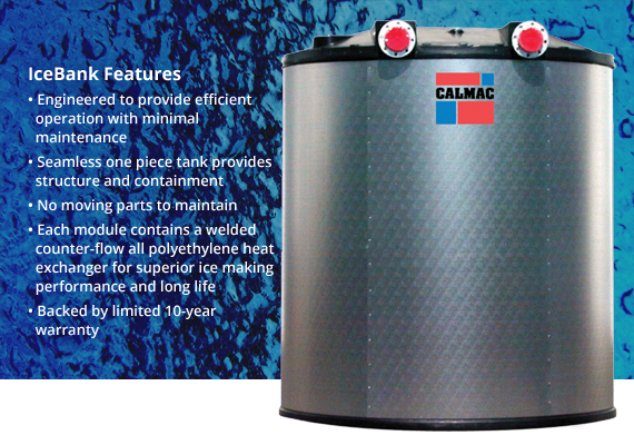
The C Model thermal energy storage tank also features a 100% welded polyethylene heat exchanger, improved reliability, virtually eliminating maintenance and is available with pressure ratings up to 125 psi.
 CASE IN POINT
The first C model project was designed by the engineering firm of Sebesta Blomberg in 2000 for Underwriters Laboratories Headquarters. View the case study.
HOW ICE BANK® WORKS
With a partial-storage system, the chiller can be 40 to 50 percent smaller than other HVAC systems, because the chiller works in conjunction with the Ice Bank tanks during on-peak daytime hours to manage the building’s cooling load. During off-peak nighttime hours, the chiller charges the Ice Bank tanks for use during the next day’s cooling. Extending the chiller hours of operation results in the lowest possible average load. The scenario below is an example of how a partial-storage system would work. (Click here for a less technical discussion.)
THERMAL ENERGY STORAGE CHARGE CYCLE
During the off-peak charging cycle, water, containing 25 percent ethylene or propylene glycol, is cooled by a chiller and then circulated through the heat exchanger inside the Ice Bank tank. The water-glycol solution that is leaving the chiller and arriving at the tank is 25°F, which freezes the water surrounding the heat exchanger inside the tank. This process extracts the heat from the water surrounding the Ice Bank heat exchanger until approximately 95 percent of the water inside the tank has been frozen solid. Ice-making has the effect of de-rating the nominal chiller capacity by approximately 30 to 35 percent. Compressor efficiency, however, will vary only slightly because lower nighttime temperatures result in cooler condenser temperatures and help keep the unit operating efficiently.
The ice is built uniformly throughout the Ice Bank tank by the patented temperature-averaging effect of closely-spaced, counter-flow-heat exchanger tubes, (see Charge Cycle). The water does not become surrounded by ice during the freezing process, but instead moves freely as ice forms, which prevents damage to the tank. A full charging cycle of an Ice Bank tank takes about 6 to 12 hours, depending upon the job criteria.

THERMAL ENERGY STORAGE DISCHARGE CYCLE
During the peak-load discharge cycle the following day (see Discharge Cycle), the glycol solution leaving the chiller is 52°F, where chiller operation is more efficient than a conventional chiller systems’ requirement of 44°F. Since the ice is downstream of the chiller, in this case, the ice will cool the glycol solution from 52°F to the coil requirement of 44°F. A temperature-modulating valve, set at 44°F in a bypass loop around the tank, permits a sufficient quantity of 52°F solution to bypass the tank, mix with 34°F solution, and achieve the desired 44°F temperature. The 44°F solution is distributed to the air-handler coil, where it cools the air from 75°F to 55°F. The solution leaving the air-handler coil is now 60°F as it re-enters the chiller and is cooled back to 52°F.

THERMAL ENERGY STORAGE BYPASS CYCLE
The temperature-modulating valve in the bypass loop has the added advantage of providing unlimited capacity control. During many mild-temperature days in the spring and fall, the chiller will be capable of providing all the necessary cooling for the building without assistance from stored cooling. When the building’s actual cooling load is equal to or lower than the chiller’s capacity, all of the system coolant flows through the bypass loop (see Bypass Cycle).

FULL STORAGE VS. PARTIAL STORAGE DESIGN STRATEGIES
With a full-storage configuration, a building’s entire cooling load is shifted to off-peak hours. The chiller only runs during off-peak nighttime hours in order to store ice for use the following day. During on-peak daytime hours, the building’s cooling is provided exclusively by the ton-hours stored within the CALMAC Ice Bank tanks the night before. Alternatively, during daytime off-peak hours, a chiller can cool the facility directly or the system can operate as a partial-storage system, depending on operation and electric rates.
(Looking for more advanced education on ice storage? Watch this technical video presentation.)
GLYCOL RECOMMENDATIONS
The ethylene-based or propylene-based glycol recommended for the solution is an industrial coolant that is specially formulated for low viscosity and superior heat-transfer properties. These contain a multi-component corrosion-inhibitor system, which permits the use of standard system pumps, seals, and air-handler coils. Because of the slight difference in heat-transfer coefficient between the water–ethylene glycol solution and plain water, the supply liquid temperature may have to be lowered by one or two degrees, which can be achieved easily by the ice.
MAINTENANCE
Maintenance of CALMAC Ice Bank tanks and the thermal energy storage system is not much different from conventional cooling. Perform chiller maintenance as required, check the health of the glycol fluid annually, check the water level in the tanks, and add biocide every other year to eliminate algae growth.